| At a glance | |
|---|---|
| Problem | Desalination in Gizo is constrained by the cost of imported energy. |
| My contribution | Led the 20-person team and designed the modular finned membrane-distillation channel, then built and led its test program. |
| Result | The finned prototype produced roughly 2.5× the permeate of the unfinned baseline; the full-scale model projected 28,600 L/day at 51% lower water cost. |
| Evidence | Side-by-side fin testing, the assembled prototype, full-scale design records, and DOE Best Build & Test honors. |
The problem
Gizo, in the Solomon Islands, is the kind of place desalination was supposed to help: surrounded by seawater, short on fresh water, and at the end of a fuel supply chain that makes every liter expensive. Conventional desalination needs either grid electricity or active heating — and the cost of water there is, mostly, the cost of that energy.
The DOE Marine Energy Collegiate Competition asks teams to put marine energy to work on real coastal problems. We chose to make water.
The reframe
The cost problem was really an energy problem — so the thermocline did the work twice.
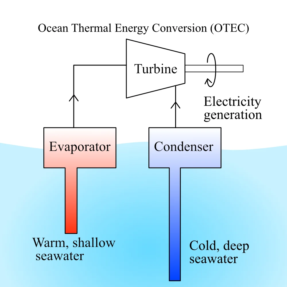
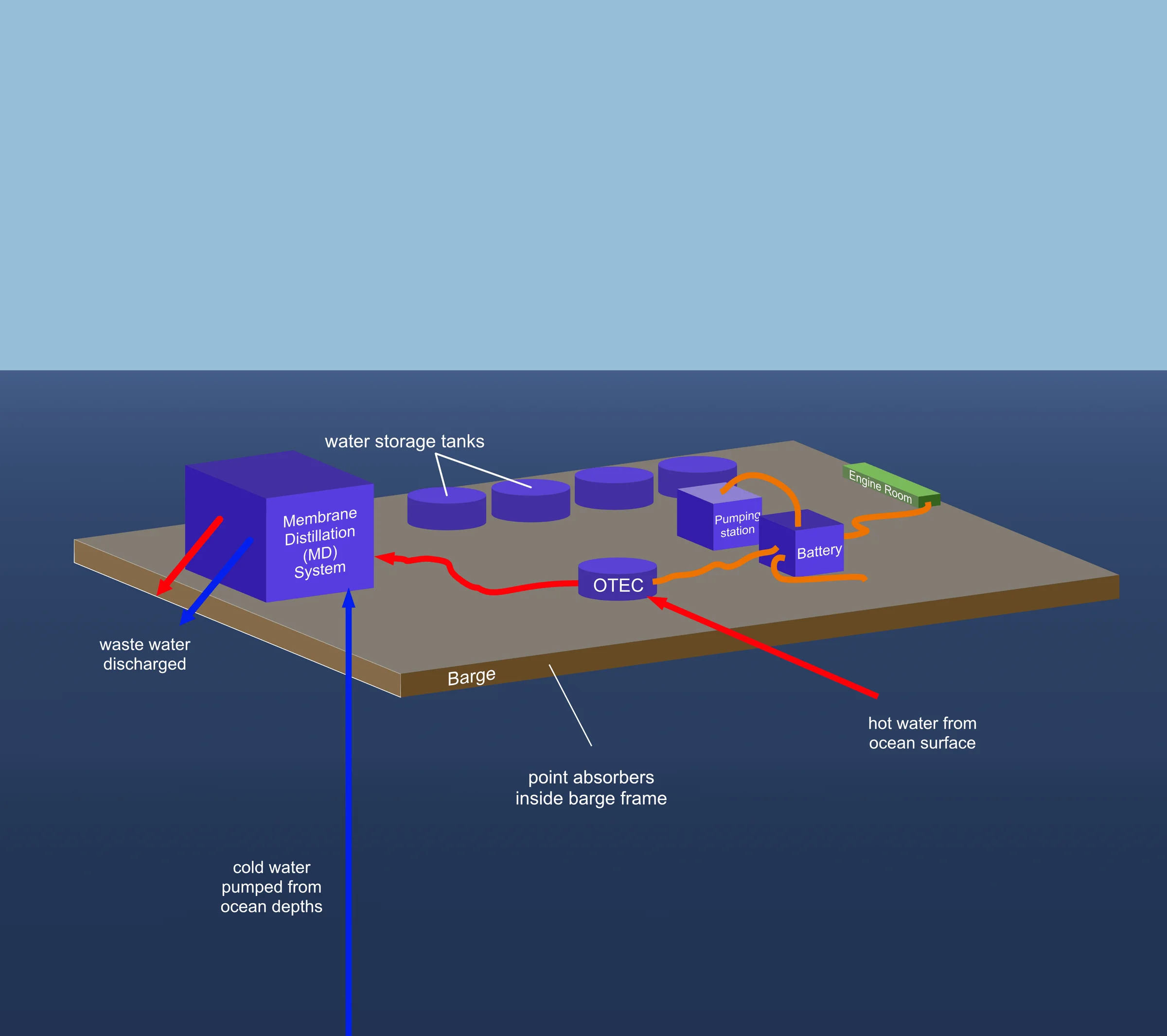
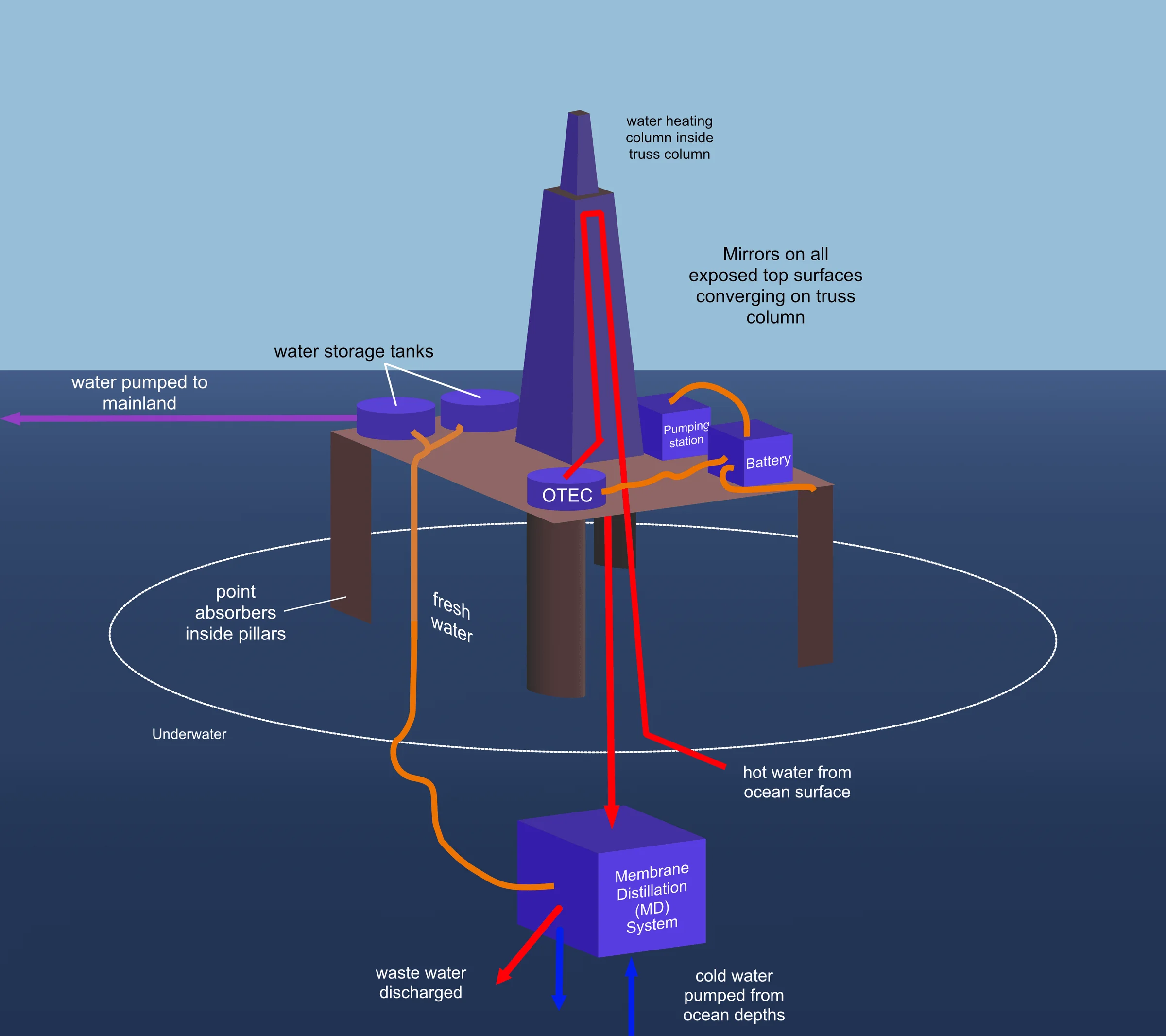
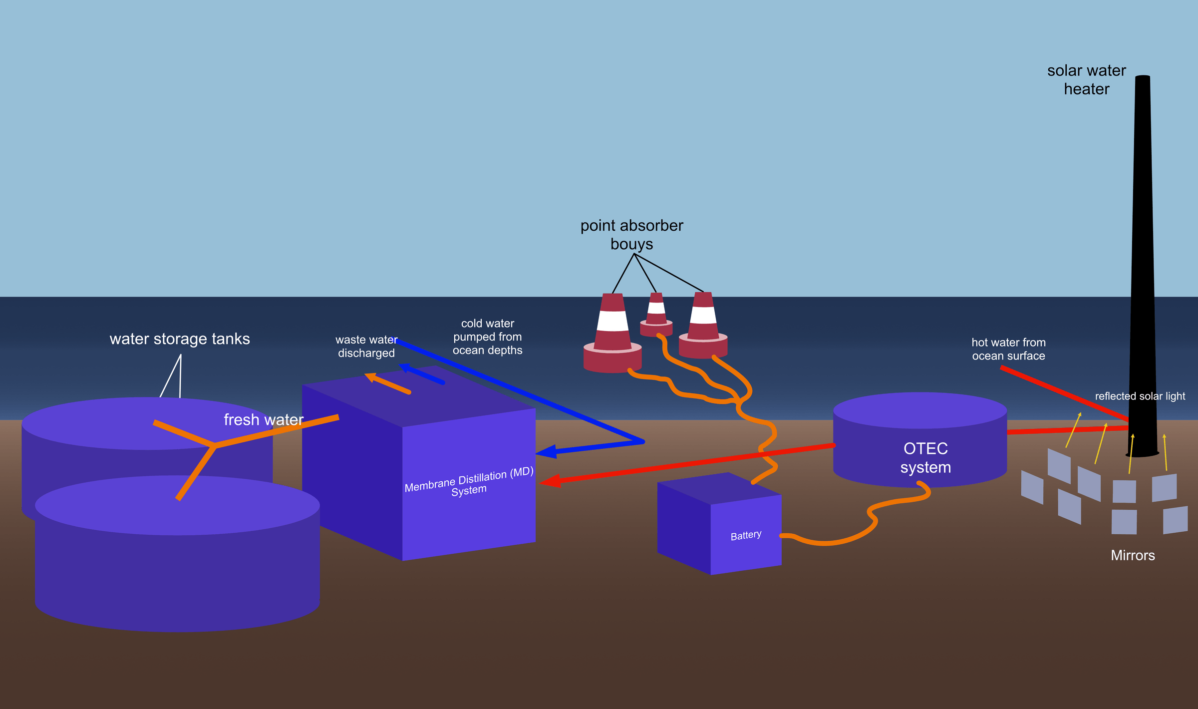
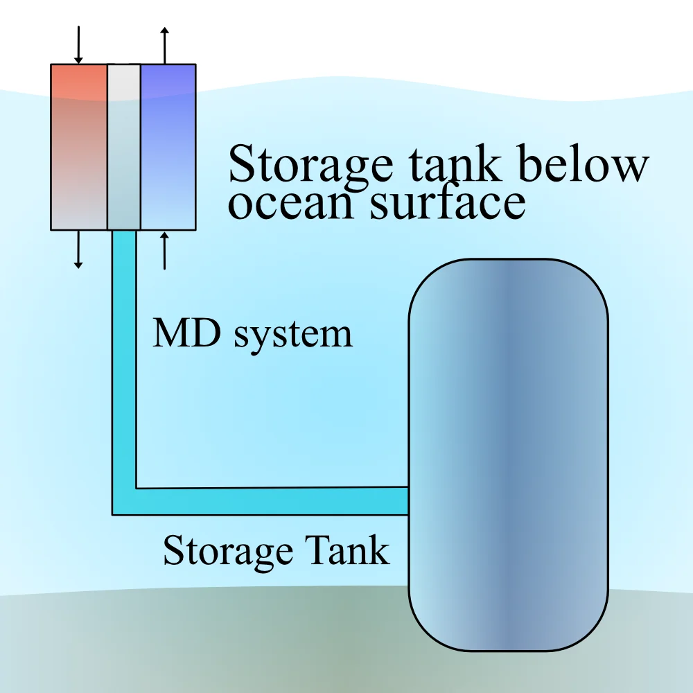
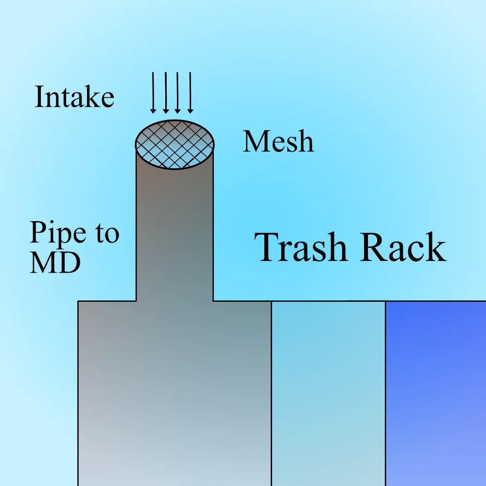
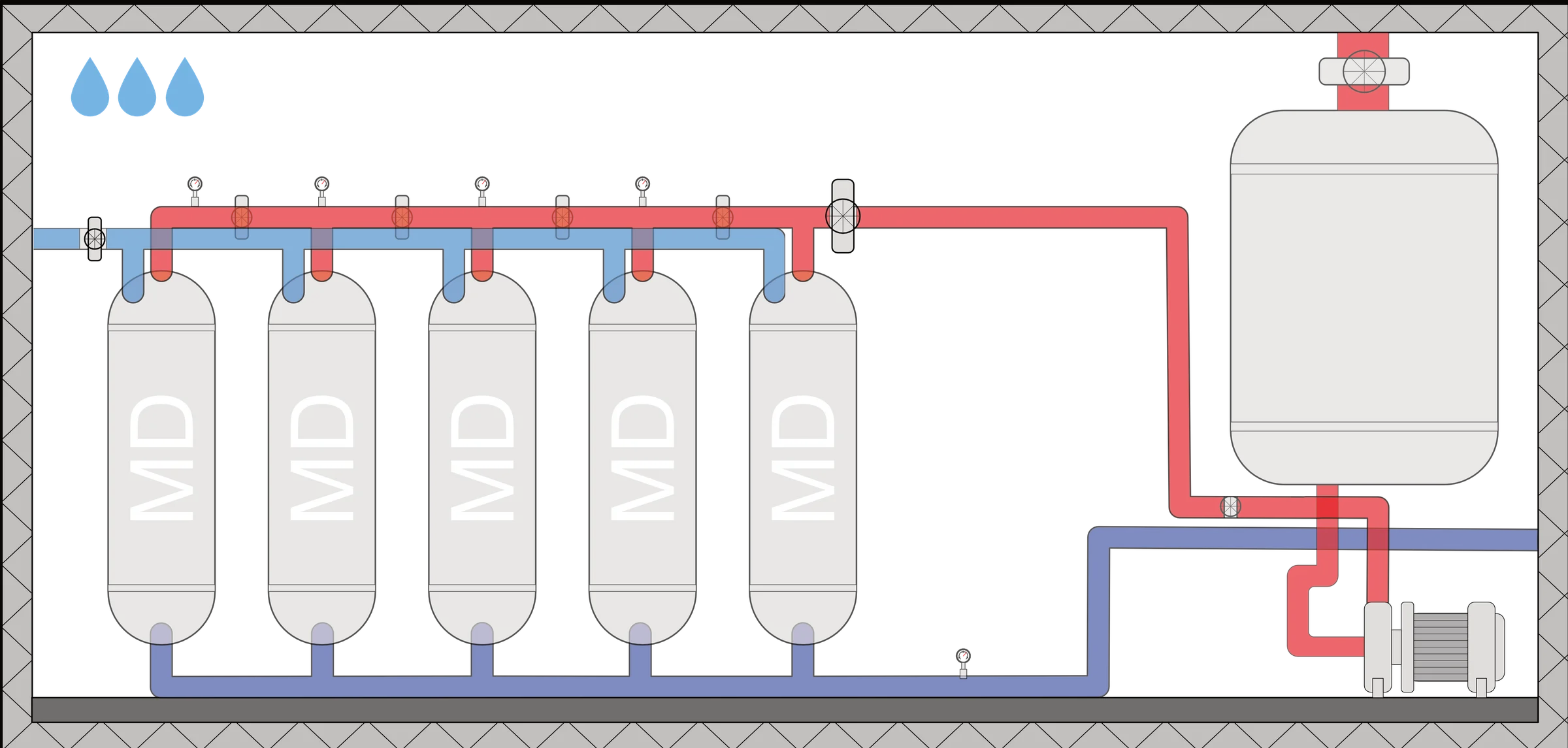
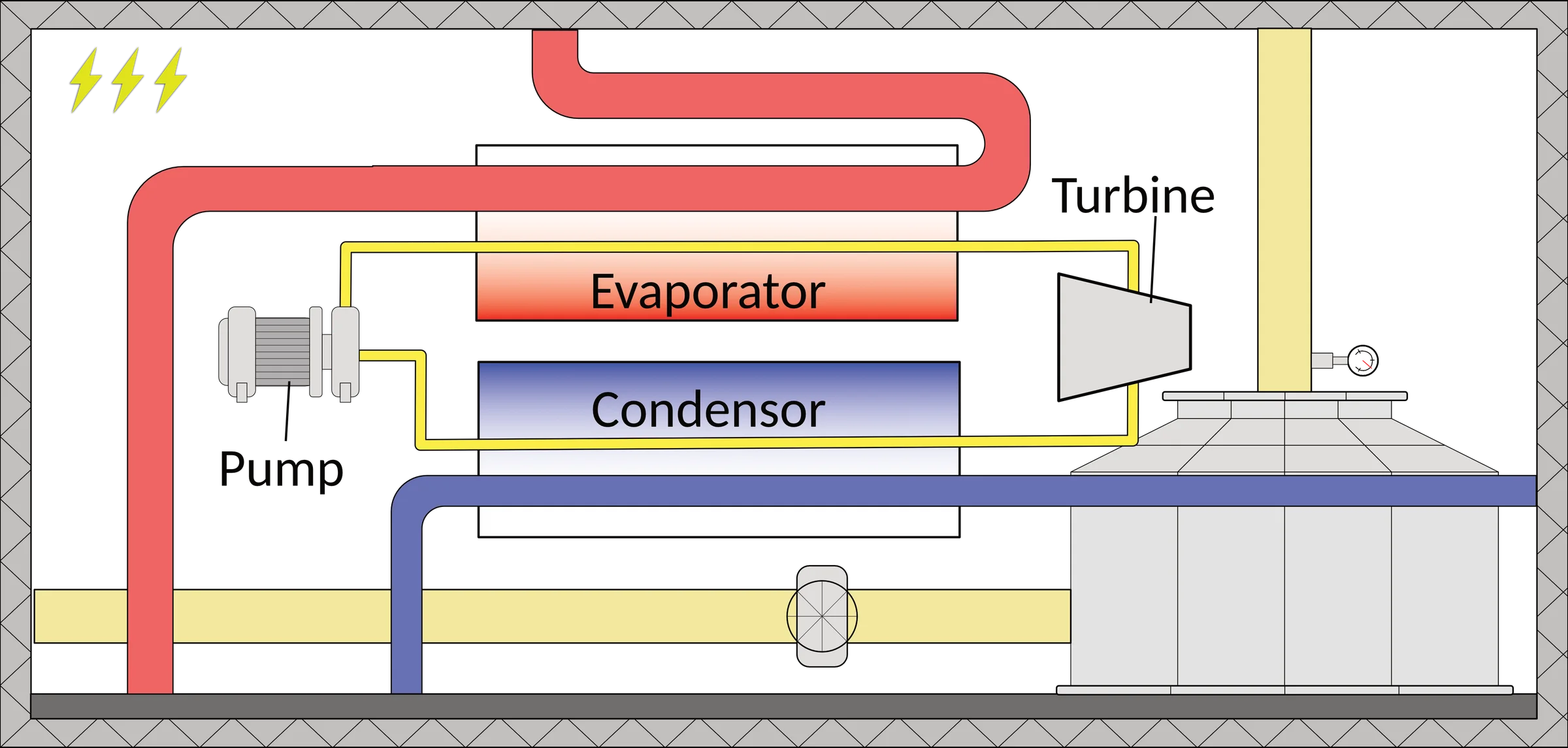
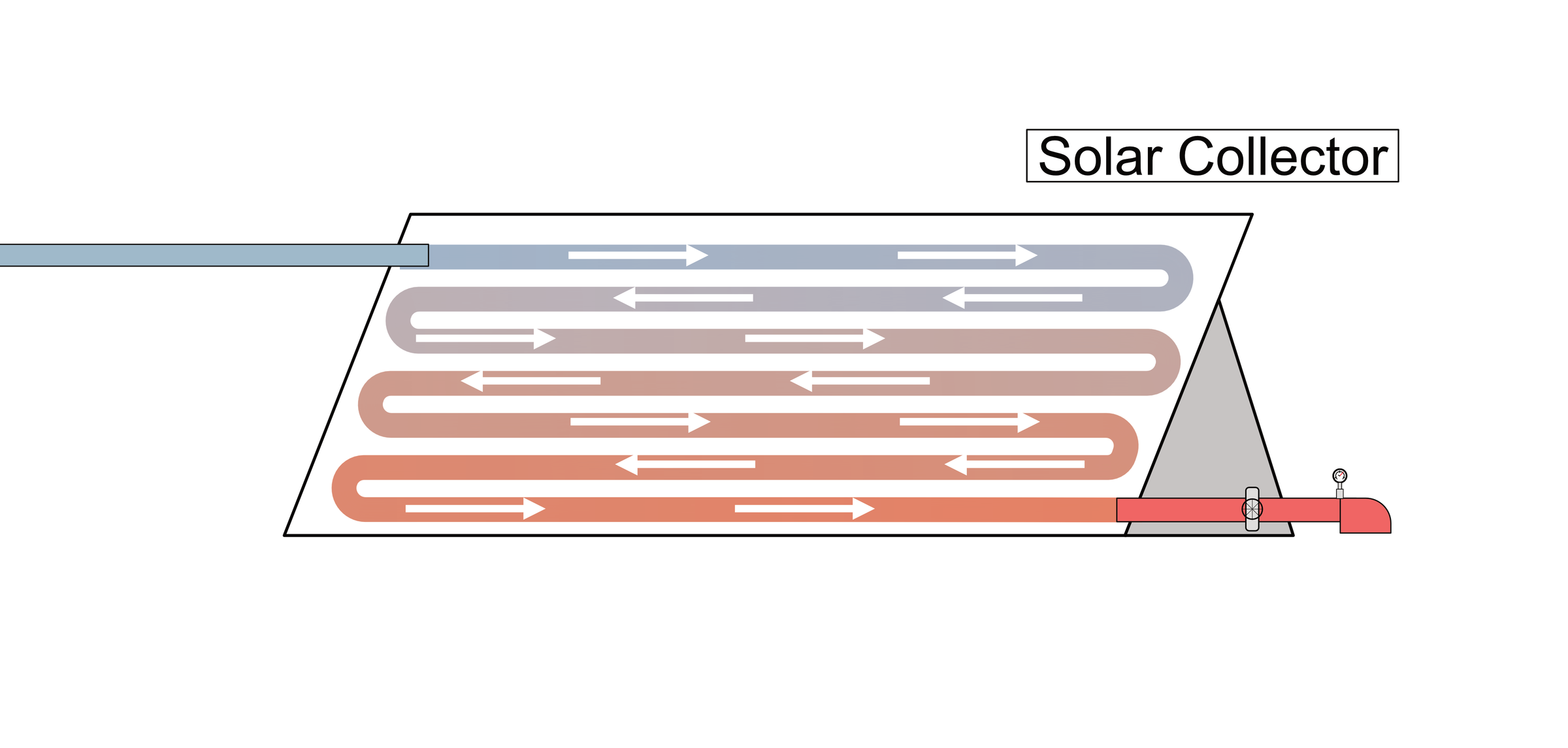
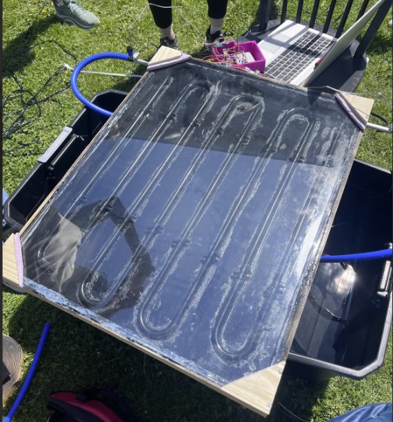
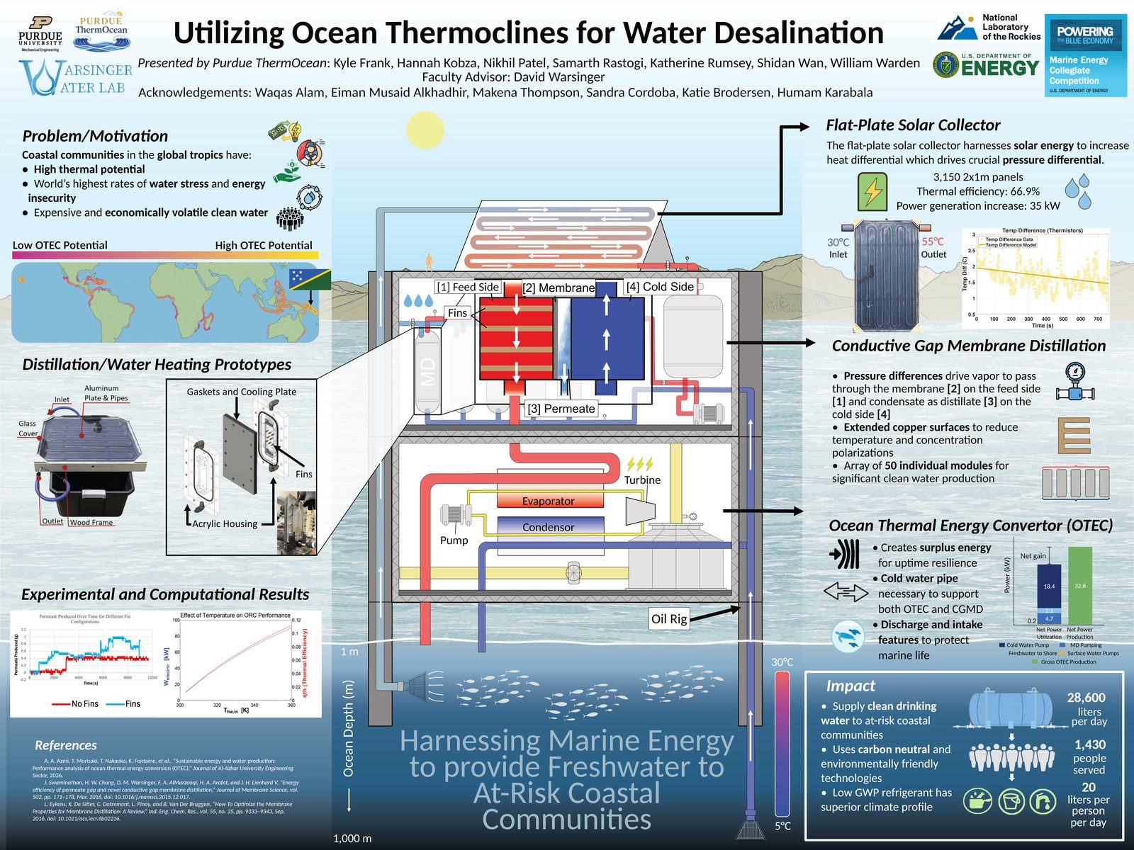
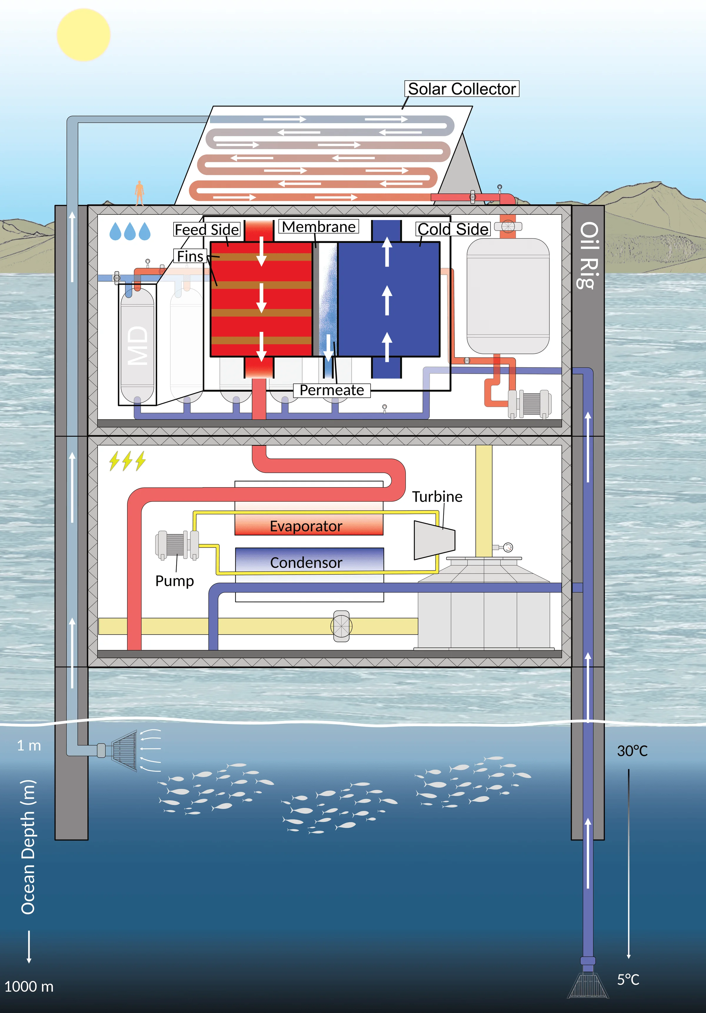
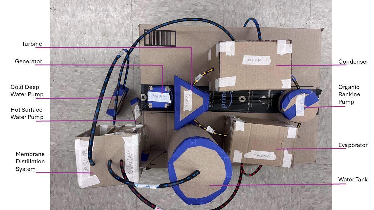
The ocean already maintains a temperature gradient — warm at the surface, cold below the thermocline. That gradient is low-grade energy, unusable for most machines but exactly the kind of heat a membrane-distillation process wants. The platform uses that gradient as its primary energy source: warm surface water drives evaporation across the membrane, while cold deep water pulls condensation. In the full-scale design, a solar collector raises the warm-side temperature to boost output. The concept needs no grid connection or fuel deliveries, so the energy bill — the thing that actually sets the price of water in Gizo — falls out of the design.
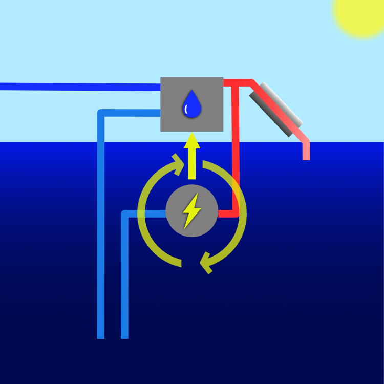
Modeled output: 28,600 liters per day, fresh water for 1,430 people, with the projected levelized cost of water 51% below the Gizo baseline.
Design
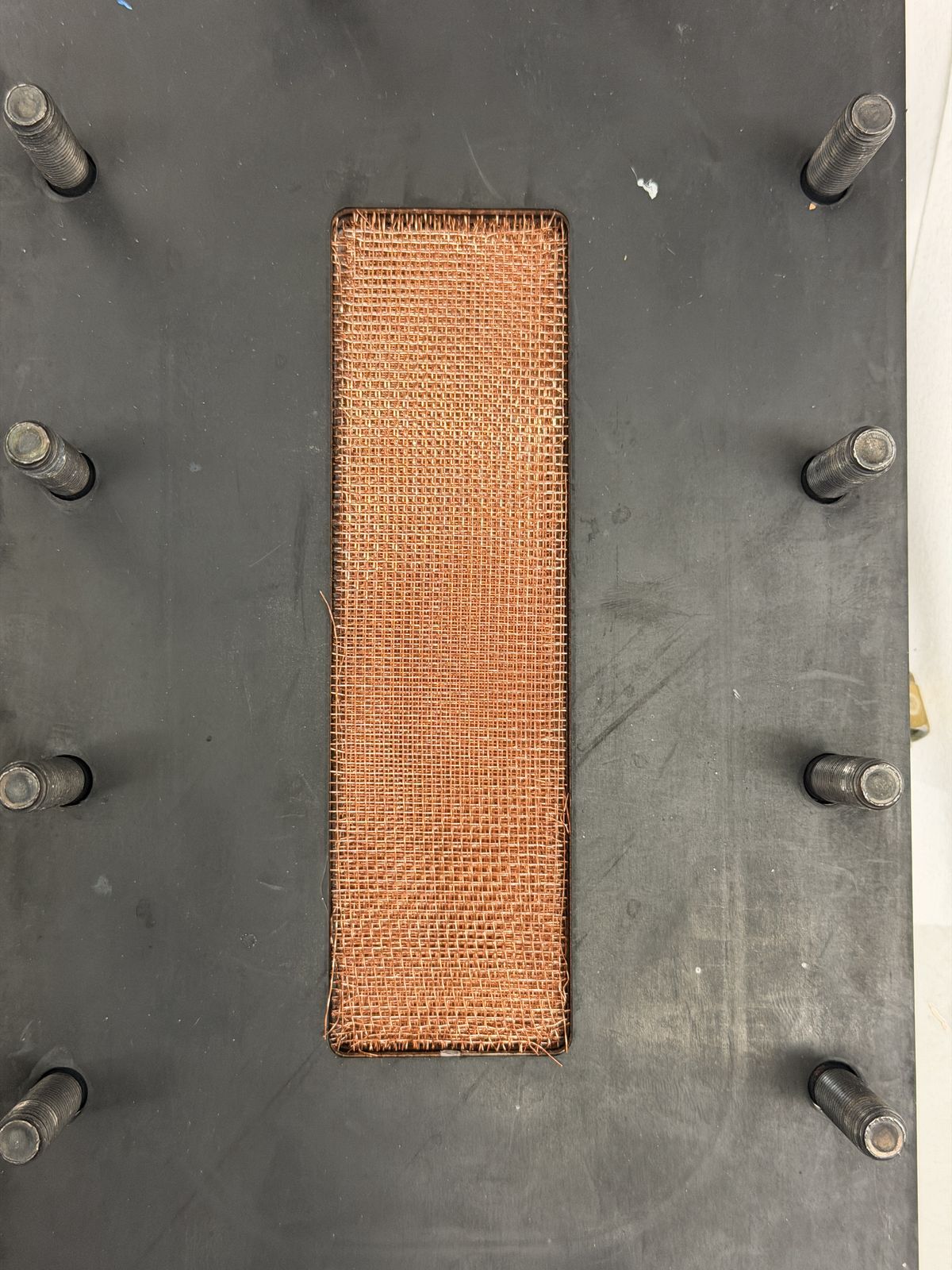
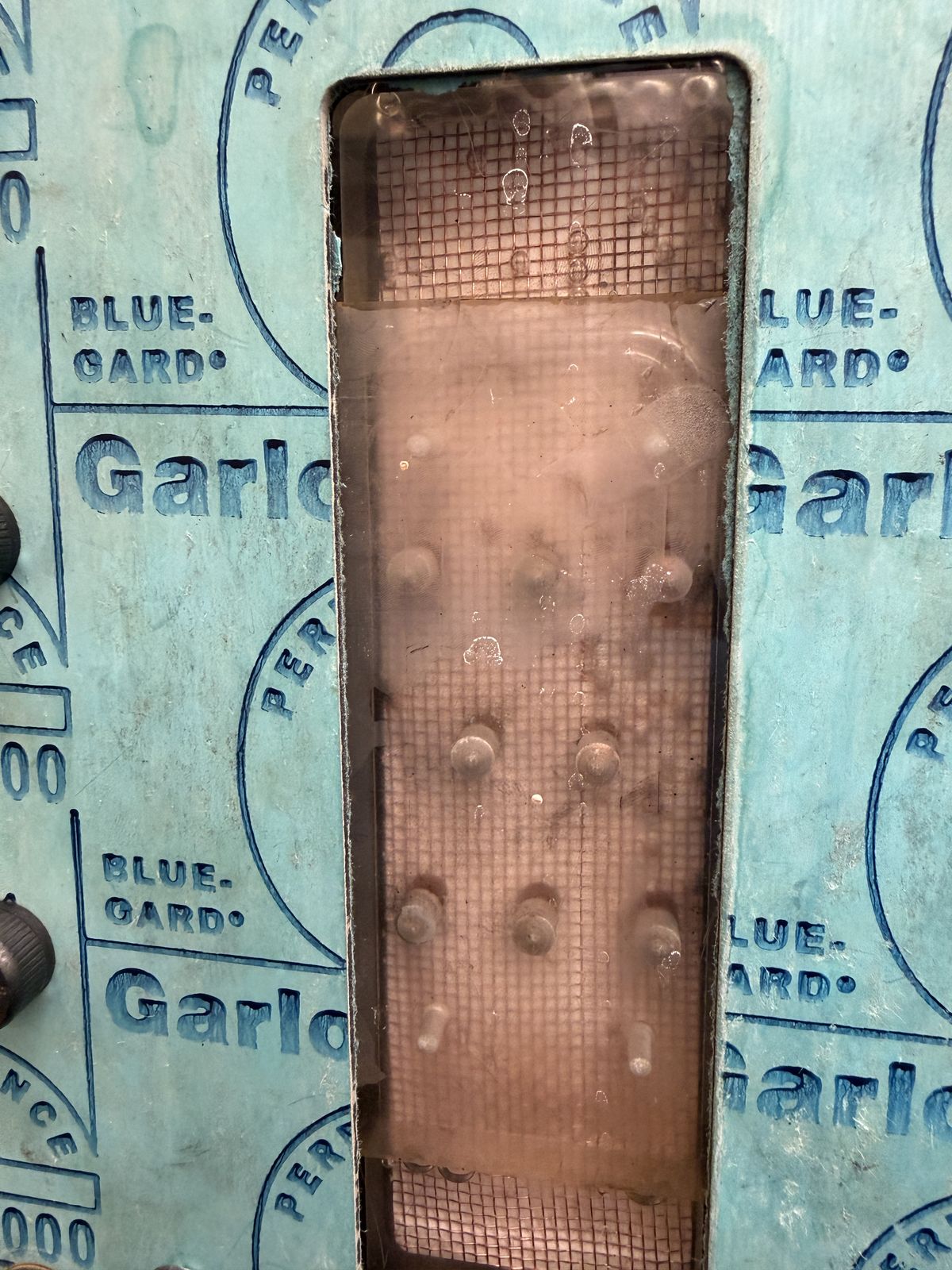
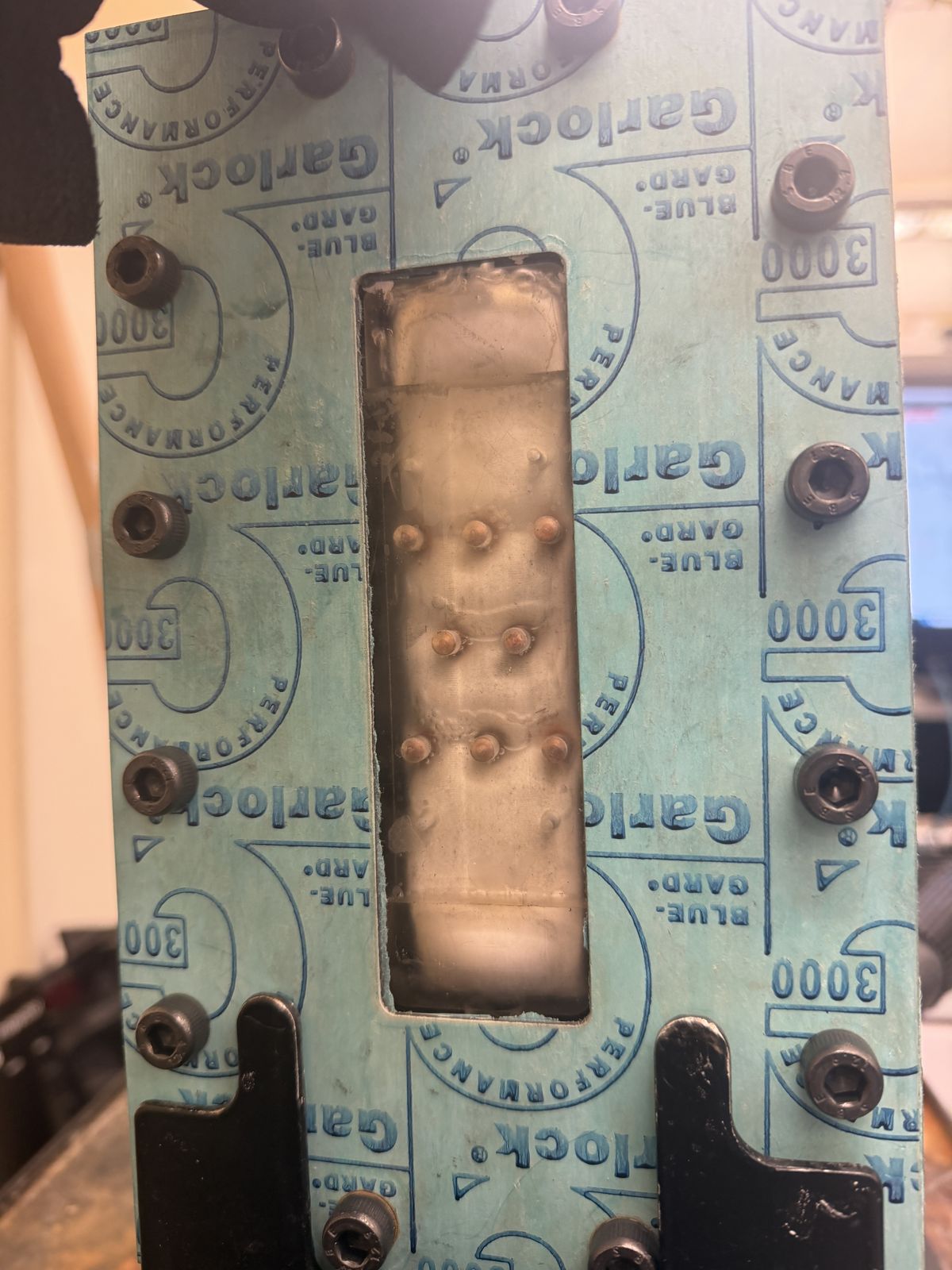
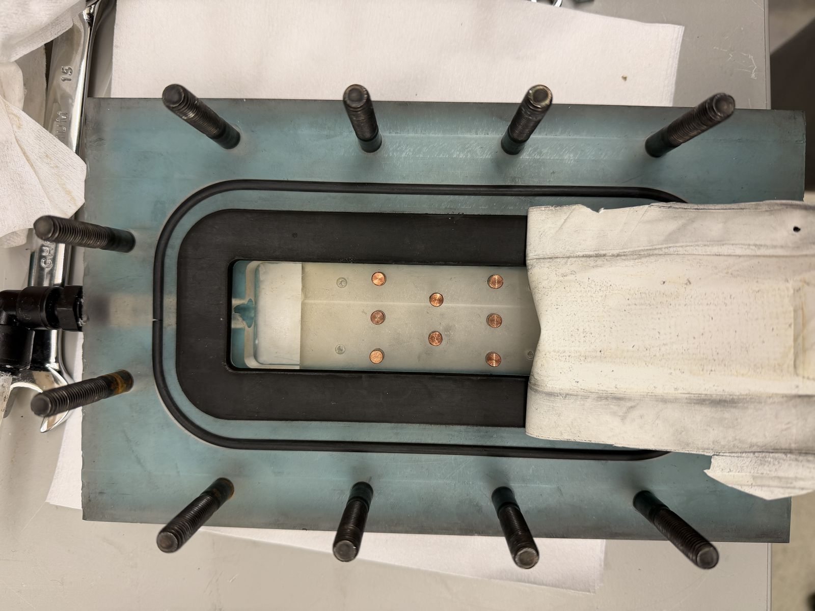
The heart of the platform is a conductive-gap membrane-distillation module. My design contribution was its finned channel: a modular geometry that supports interchangeable fin configurations, so the team could test heat-transfer trade-offs in hardware instead of arguing about them in simulation.
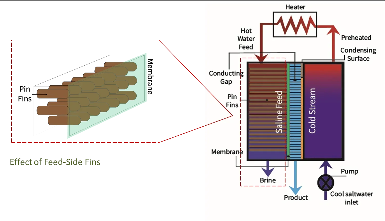
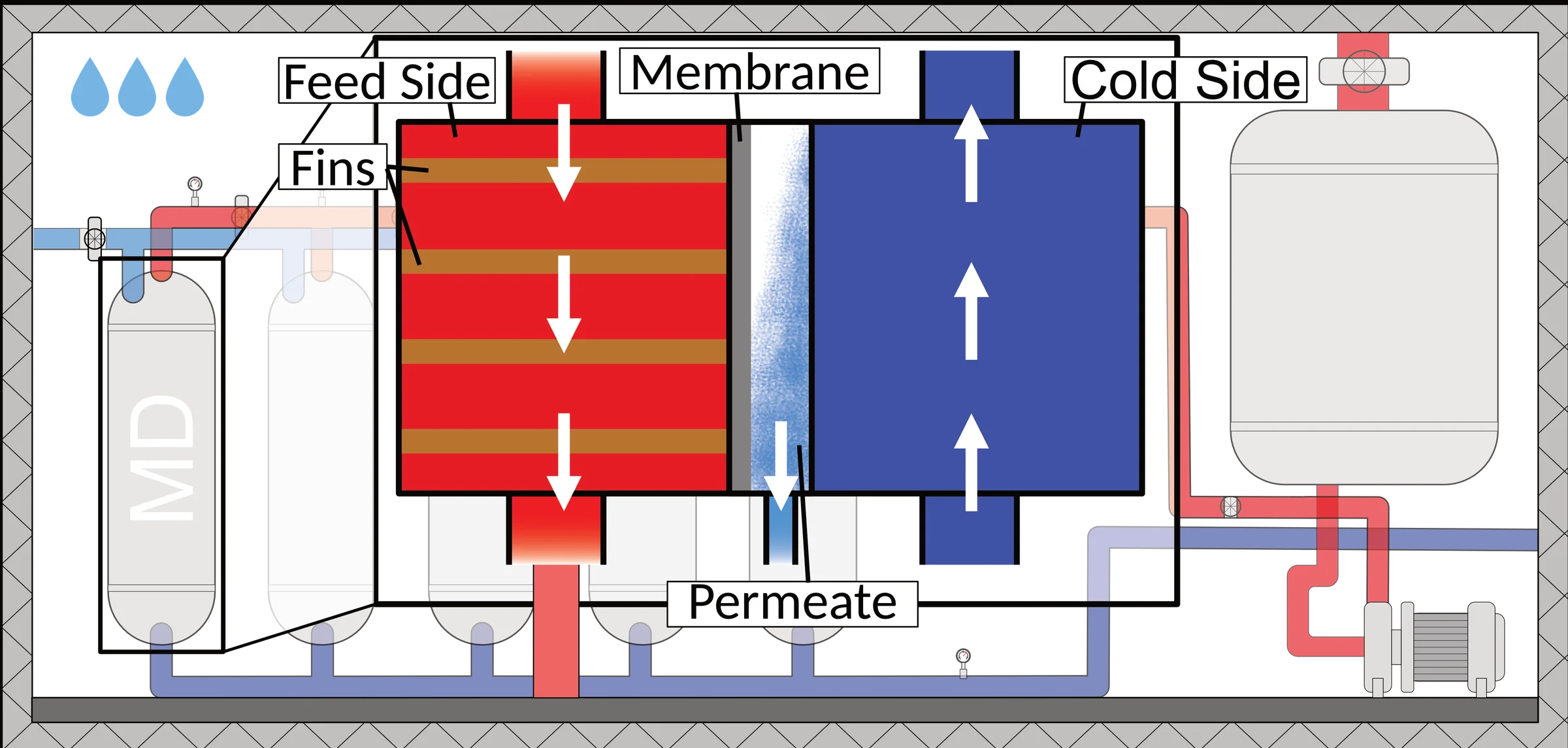
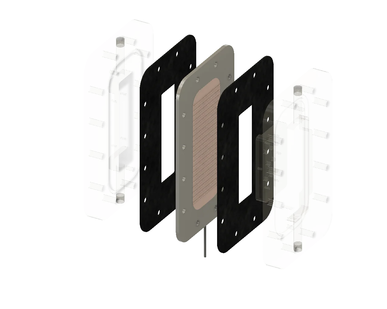 Feed housingGasketFinned plateMembraneGasketCold housing
Interchangeable fins turned a design argument into a test matrix. When the geometry is swappable, you don’t have to be right the first time — you have to be measurable.
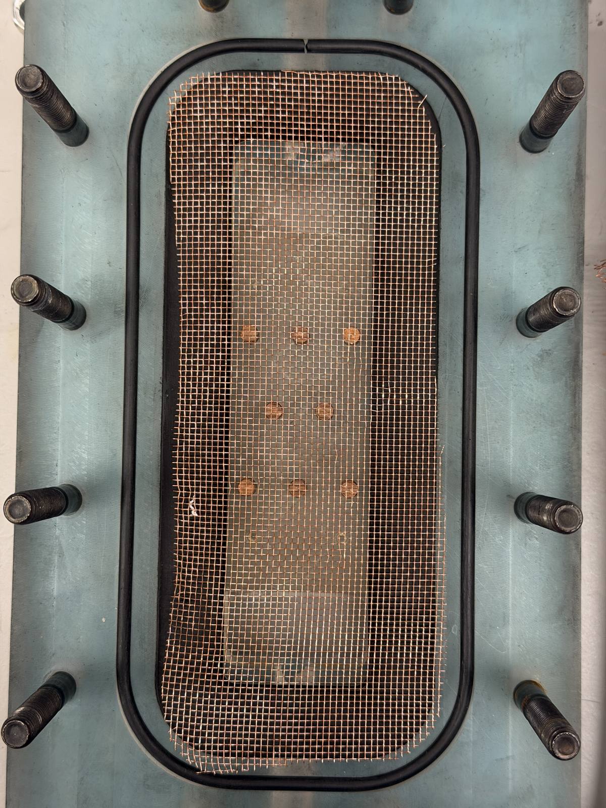
Full-scale, 50 of these modules run in parallel — 1,250 m² of active membrane area producing 5.55 LMH at a gained output ratio of 1.80.
Build & test
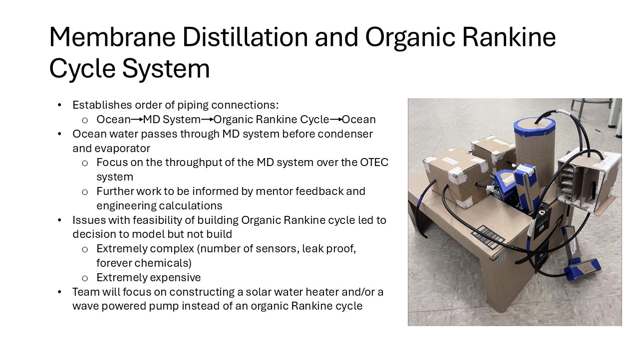
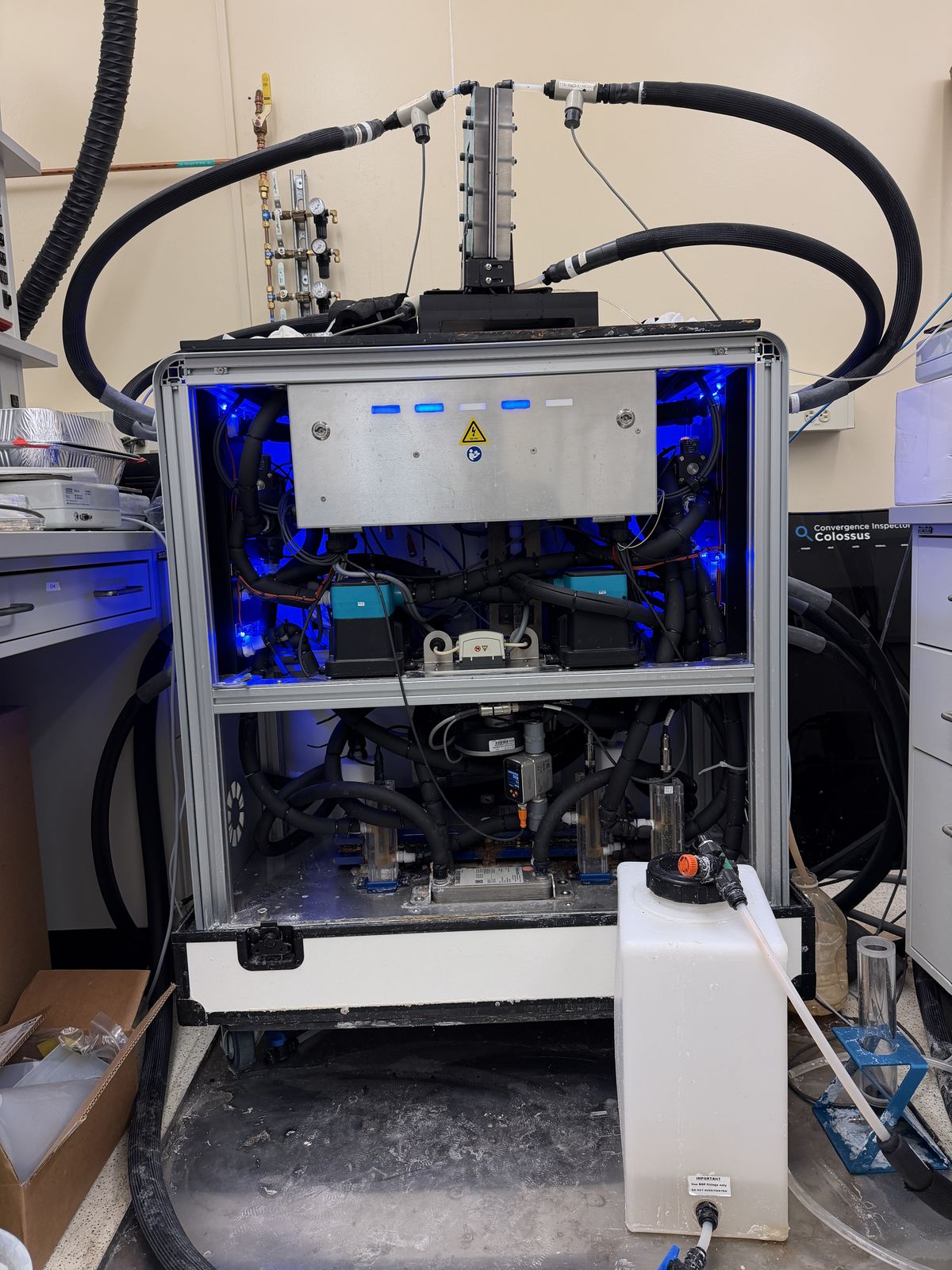
We built the lab-scale prototype and I led its testing. That end of the project — machining, sealing, instrumenting, running — is where the design either holds up or doesn’t.
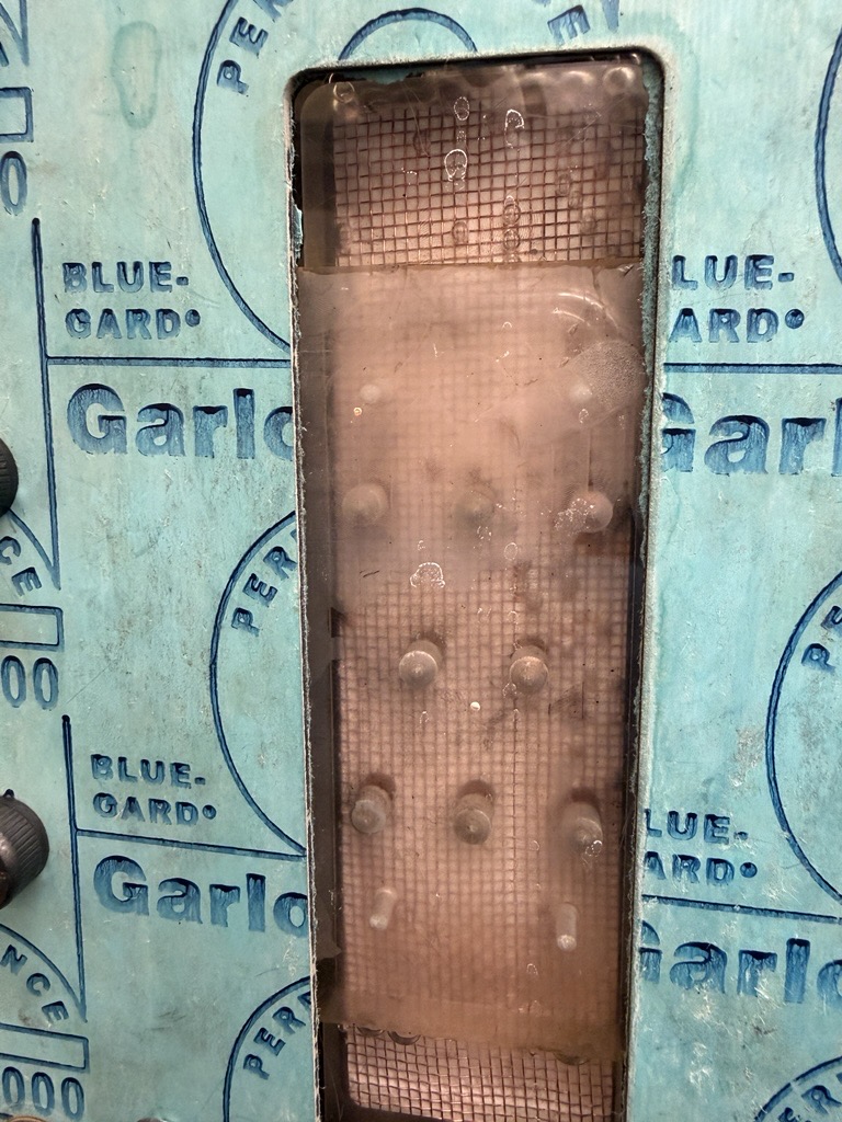
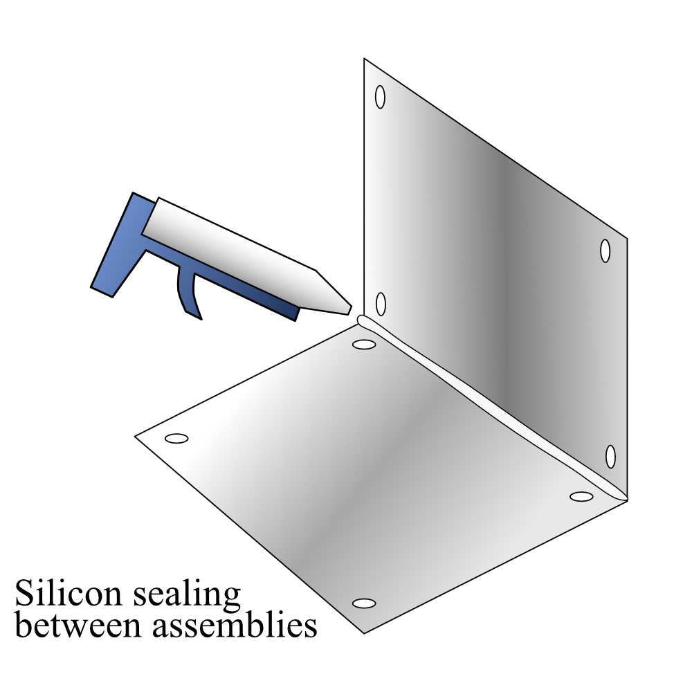
The modular sandwich architecture — acrylic housings, gaskets, membrane, finned plate — meant the module was repeatedly assembled, tested, disassembled, and reassembled with different fin configurations. That flexibility was the point of the design, but it made sealing a transient problem. The initial plastic swivel joints ruptured under pressure, sending us back to research better fittings that could swivel and still hold. The food-grade replacements leaked too — five hours of in-lab troubleshooting before we found a joint configuration that sealed reliably through repeated coupling cycles.
The modular architecture was the right call, but modularity taxes every seal. Five hours of chasing leaks through swivel joints taught us that the connection is the design, not the thing it connects.
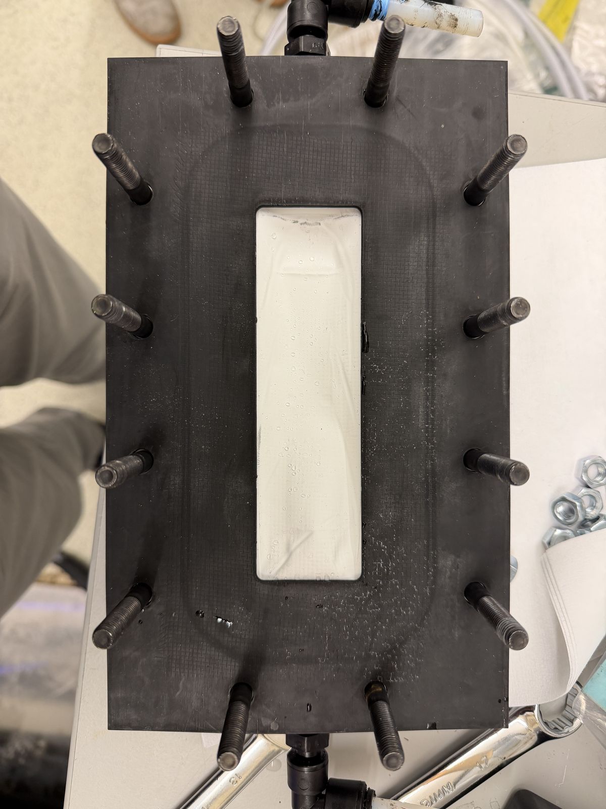
A CNC error on one housing left a feature shallower than spec. Rather than re-machine, we iterated on the gasket stack — adjusting thicknesses until the existing housing sealed at pressure. That kind of recovery matters more than getting it right the first time.
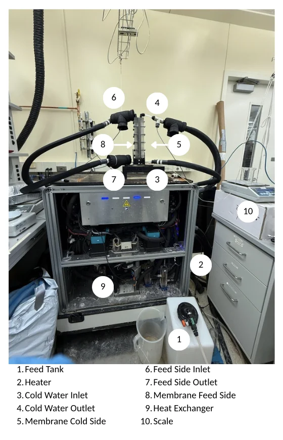
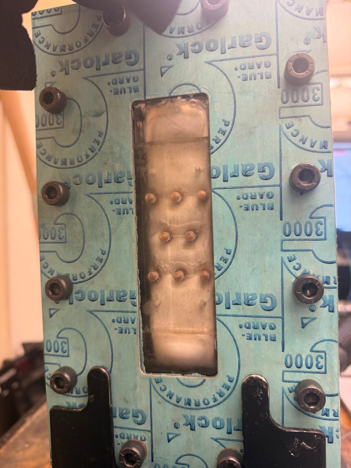
With sealing solved, we ran the comparison that the whole finned-channel design existed to make possible: fins versus no fins, same module, same conditions.
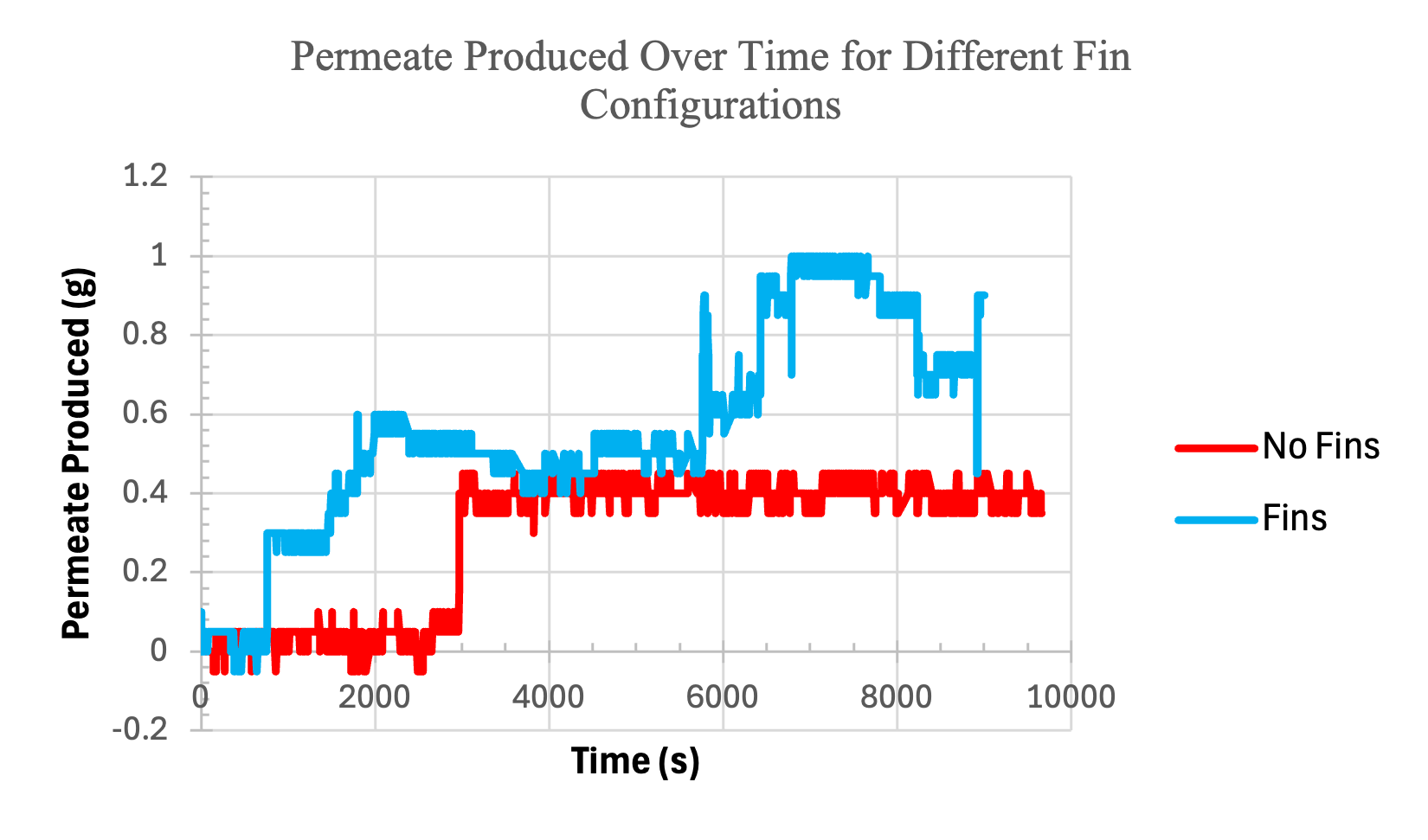
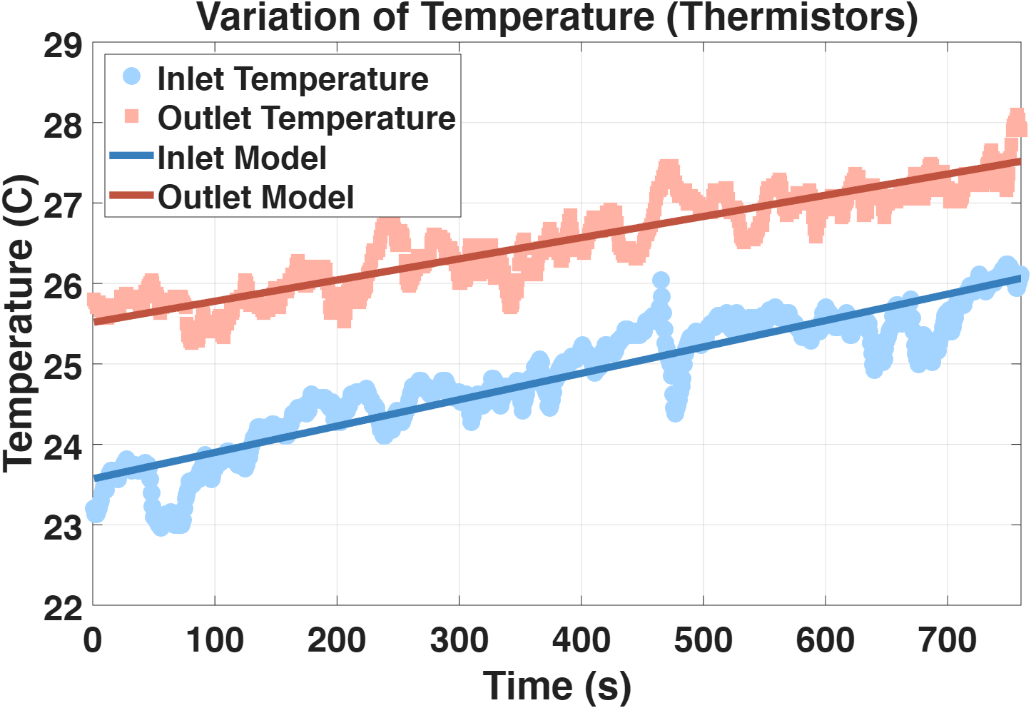
The finned configuration produced roughly 2.5 times the permeate output of the unfinned baseline. The fins enhance flow mixing, thin the boundary layer, and increase both heat and mass transfer across the membrane — exactly the mechanism the design predicted, now measured.
It held up. The team won Best Build & Test honors against 27 teams at the DOE Marine Energy Collegiate Competition, a judgment specifically of prototype design and testing rigor.
Leading the team
Twenty undergraduate and graduate researchers, two DOE competitions running in parallel. I set MECC’s technical direction, drove the industry-mentor strategy, and aligned the Hydropower Collegiate Competition planning with its incoming lead. The budget — $21,000 in staged competition funding tied to proposal deliverables — I built and managed first, then deliberately delegated.
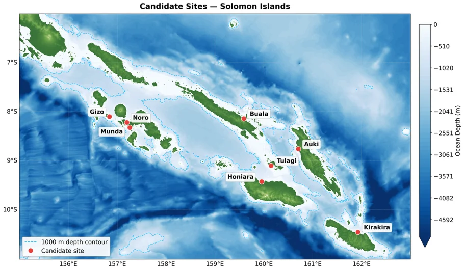
Beyond the engineering, I owned the business plan: site selection, stakeholder mapping, financial modeling, and the deployment roadmap we presented to DOE judges. Gizo wasn’t a default — it was selected from eight candidate sites in the Solomon Islands by overlaying bathymetric data with population density, existing water infrastructure, and proximity to the 1,000-meter depth contour the cold-water intake requires.
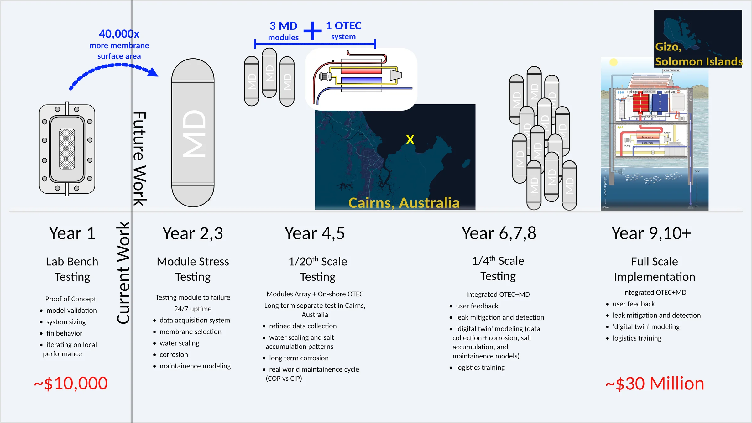
The model we pitched: an Independent Water and Power Producer that sells freshwater to the community at below the next-best-alternative price, funded by impact investors who gain a tax break. No financial burden on the community; profits reinvested into scaling and research.
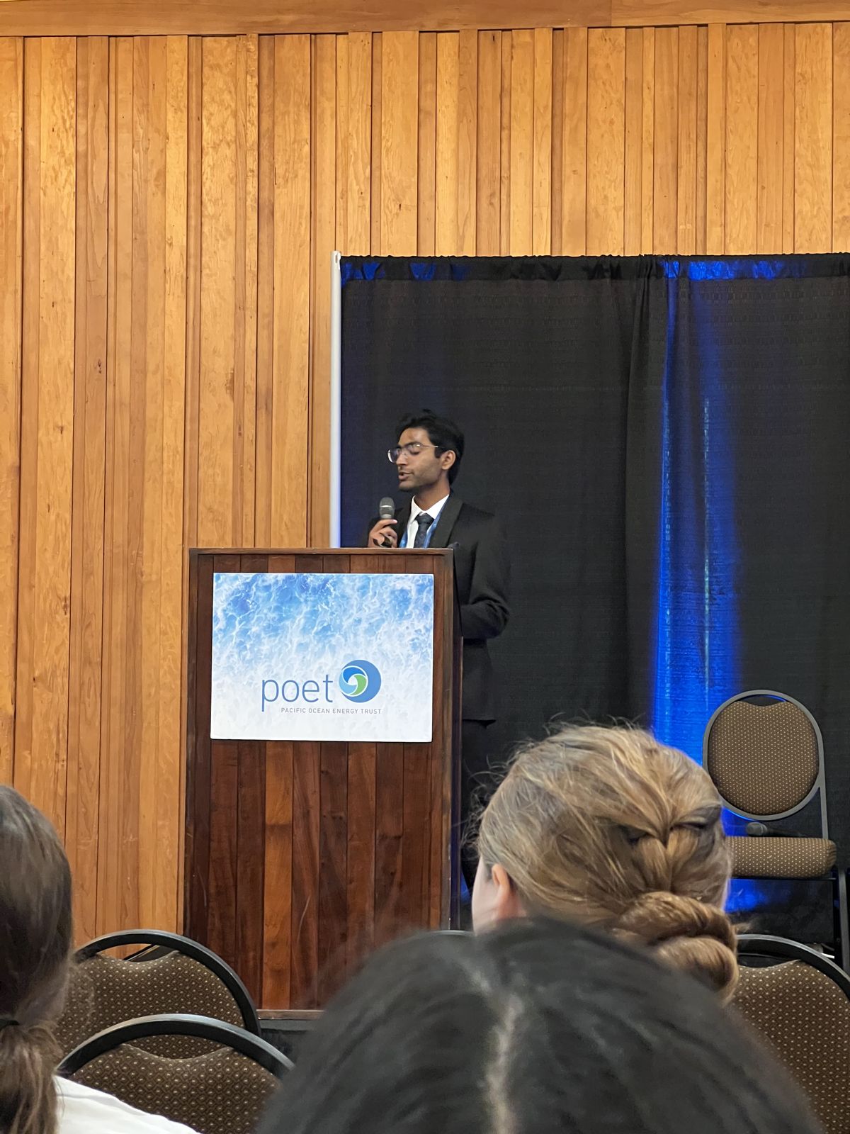
The work also traveled: we co-authored and presented “Utilizing Ocean Thermoclines for Water Desalination” at NCUR 2026, pitched at the OREC MECC conference in Portland, and ran three K-12 outreach events that put hands-on builds in front of 226 students.

Lessons
The project’s central lesson is the reframe itself: the most expensive part of a system is often an energy flow wearing a cost costume. Finding the gradient that’s already there — and using it twice — beat every version of the design that tried to fight thermodynamics head-on.